http://plc-kita.blogspot.com/ February 2010 | PLC.com

Sunday, February 21, 2010

AS-Interface... Let the Sensors Do the Talking - Part 2


Let's continue with our AS-Interface discussion. You will remember from last time that we discussed the physical hardware features. we pointed out that up to 31 sub devices can be connected to 1 main device. maximum separation between them can be up to 100 meters...
that's a far distance, isn't it?

Regarding speed, it's 'reasonably' quick. Each device added to the network increases the time needed for communication. Each device requires a maximum of 150 us to talk. Plus the network needs 300 us to
do some housekeeping.
So, a network with the maximum 31 devices needs
(31 x 150) + 300 = 4650 + 300 = 4950 us or 4.95 ms

A network of only 15 devices would therefore require:
(15 x 150) + 300 = 2250 + 300 = 2550 us or 2.55 ms

As you can see from the above, less units mean a quicker speed. If we have 15 devices connected we can pretty much guarantee that they will be spoken to every 2.55 milliseconds. Not bad...

Now let's see what actually gets sent during each message transfer and  understand what goes on throughout the network.


Messages sent throughout the network are called telegrams. The main unit sends as many telegrams as there are connected and active sub devices on the network. So, if we have 25 devices connected the main
unit will send 25 telegrams.

Each sub unit will be sequentially polled by the telegrams from the main unit. The sub unit with the lowest address gets polled first and then the next higher, etc. If a sub unit becomes disconnected the main
unit will notice within 1 cycle time (a maximum of 5 ms).

An AS-Interface telegram sends/receives a message in both directions  with the sub units. First the main unit sends a request to the subs (a write command) and then the subs reply (a read command) all within a
single telegram.

So, we have a main call, then a main unit pause, then a sub unit reply and a sub unit pause.

A telegram will actually look like the below if we break it down into digestible pieces:

St Cb A4 A3 A2 A1 A0 I4 I3 I2 I1 I0 Pb Eb

St= Start Bit. This is always a 0. It's a 1 when not transmitting...

Cb= Control bit. This controls if we're working with 'data/parameter access' or 'command access'. It is set to 0 for data/parameter access and 1 for command access.

A4-A0= Address bits. This is the address of the sub unit we are talking with. There are 5 bits here because 11111 in binary is 31.
So we can talk to any of the sub units just by setting it's address here.

I3-I0= Information bits. This is the actual information that we are sending to the sub unit... depending upon the command.
Pb= Parity bit. this is used for error checking. If there are an even
number of 1's in the message this is a 0. if there are an odd number of 1's in the message this is a 1.

Eb= End bit. This terminates the message and is always a 1.

Now, let's put together a telegram where we are talking with only one  sub unit. It will look like the below string of data:

main unit call
St Cb A4 A3 A2 A1 A0 I4 I3 I2 I1 I0 Pb Eb
main unit pause
3 to 10 bit times
sub unit response
St I3 I2 I1 I0 Pb Eb
sub unit pause
1 bit time

Remember that the above communication happens in 1 telegram. If there were 25 sub units connected to the main unit it would still all be sent in only 1 telegram.

Well, hopefully we can see how easy this network is to understand. Not much to it when we break it down into pieces and analyze the results.

Saturday, February 20, 2010

Transformer

Introduction to Transformers


Two coils that have mutual inductance make up a transformer. The coil connected to the source of energy is called primary coil and the other is called secondary coil. It is useful in that the electrical energy can be transferred from one circuit to another without direct connection. It can also change the voltage level from one level to another level depending on the windings ratio of the primary and secondary coils. It can only be used with AC voltage because no voltage is induced if there is no change in magnetic field.
The increase of the inductance of coils can be done by windings the coils on magnetic material like iron core.

Turns Ratio, Voltage and Current
In a varying magnetic field, the voltage induced in a coil is proportional to the number of turns in the coil. If the coils are wound in the same field, the induced voltages will be proportional to the number of turns in each coil.

Vs = Vp(Ns/Np) 

where

  • Vs = secondary voltage 
  • Vp = primary voltage 
  •  Ns = number of turns on secondary 
  •  Np = number of turns on primary


If no current is taken from the secondary(open circuit), the current that flows in the primary is called magnetizing current of the transformer. Typically, the transformer is designed in such a way that the power consumed by it is only to overcome the losses in the iron core and in the resistance of the wire with which the primary is wound.
If the secondary is connected to the load, the current on the primary is given in the formula below assuming that the entire primary current is caused by the secondary load.
Ip = Is(Ns/Np)
where Ip = primary current
Is = secondary current
Ns = number of turns on secondary
Np = number of turns on primary

Impedance Matching
 
Many devices need a specific value of of load resistance for optimum operation. The impedance of an actualload that is to dissipate the power may differ from this value, so a transformer is used to change the actual load into an impedance of the desired value. This is called impedance matching.
Np/Ns = Square root(Zp/Zs) where
Np = number of turns on primary
Ns = number of turns on secondary
Zp = primary impedance required
Zs = impedance load connected to the secondary

Example : A transistor for audio amplifier requires a load of 200 ohms for optimum operation and is to be connected to a loudspeaker with an impedance of 4 ohms. The turn ratio, Np/Ns required will be Square root (200/4) = 7.1 i.e. the primary must have 7.1 times as many turns as the secondary.


Construction of Transformer
 
Two common types of construction are SHELL type and CORE type. In the SHELL type both windings are placed on the inner leg, while in the CORE type the primary and secondary windings may be placed on separate legs. They are usually designed so that the magnetic path around the core is as short as possible.

The material used for the core is usually silicon steel, built up by laminations, insulated from each other by a layer of coating. The number of turns required is inversely proportional to the cross sectional area of the core. Typically, the windings of small power transformers usually have 6-8 turns/volt on a core of 1 square inch cross section and have a magnetic path of 10-12 inches in length. A longer path or smaller cross section requires more turns/volt and vice versa.

The material used for the core is usually silicon steel, built up by laminations, insulated from each other by a layer of coating. The number of turns required is inversely proportional to the cross sectional area of the core. Typically, the windings of small power transformers usually have 6-8 turns/volt on a core of 1 square inch cross section and have a magnetic path of 10-12 inches in length. A longer path or smaller cross section requires more turns/volt and vice versa. 


Friday, February 19, 2010

555 oscillator


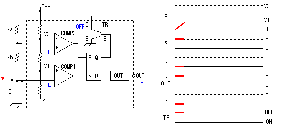
This is the square wave oscillation circuit which used NE555. 555 was developed as the IC for the precision timer. It is compactness (DIP 8 pins) and it is simple composition. It is often used for the timer circuit, the oscillation circuit because of precision well the operation
 

NE555 is composed of the voltage comparators, the flip-flop and the transistor for the discharge. The composition is simple, but it is excellent one.
Three resistors are connected with the inside in series and the power supply voltage(Vcc) is divided in 3. This composition is an excellent point. 1/3 with power supply voltage is applied to the positive input terminal of the comparator (COMP1) and the voltage of 2/3 is applied to the negative terminal of the comparator (COMP2). When the voltage of the trigger terminal(TRIGGER) is less than 1/3 of the power supply voltage, the S terminal of the flip-flop(FF) becomes H level and an FF is set. When the voltage of the threshold terminal(THRESHOLD) is more than 2/3 of the power supply voltage, the R terminal of the FF becomes H level and an FF is reset.


The condition immediately after the turning on
 

Immediately after a power supply voltage is supplied, as for the FF, the Q becomes H and becomes L condition. Because is the L, TR is in the OFF condition and the electric current flows through the resistor of Ra and the Rb at the capacitor (C). Immediately after a power supply voltage is supplied, the electric charge isn't stagnant in capacitor(C). So the voltage of the X point starts from 0V. Because the X point is lower than V1 of COMP1, the S terminal of the FF becomes the H condition. With this, the Q becomes H, becomes L condition but they are in the condition already. On the other hand, because the COMP2 (+) terminal is lower than V2, the output of COMP2 becomes the L and the FF is stable in this condition.

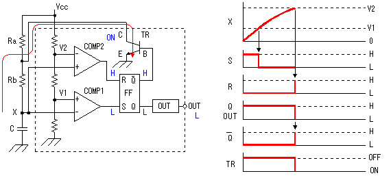
Output's reverse (1)

When the voltage of the X point crosses V1 of COMP1, the output of COMP1 becomes L. However, this change doesn't change the condition of the FF. The output of COMP2 becomes the H condition when the voltage of the X point rises more and reaches V2 of COMP2. With this, the R terminal of the FF becomes H and the output state of the FF reverses. The Q becomes the L condition and becomes the H condition. At this time, OUT changes into the L from H. Because became the H condition, TR becomes the ON condition. Because the interface of Ra and the Rb becomes the grounded condition, the electric current which was flowing through C so far through Ra and the Rb gets not to flow through capacitor(C). The electric charge which was stagnant in capacitor(C) begins the discharge through the Rb and TR. Voltage of the X point begins to go down with this discharge. Because voltage of the X point goes down, the voltage of the COMP2 (+) terminal becomes less than V2 and the R terminal of the FF changes into the L condition from H. This change doesn't change the condition of the FF.
It is only in a little time that the R terminal of the FF becomes the H condition.


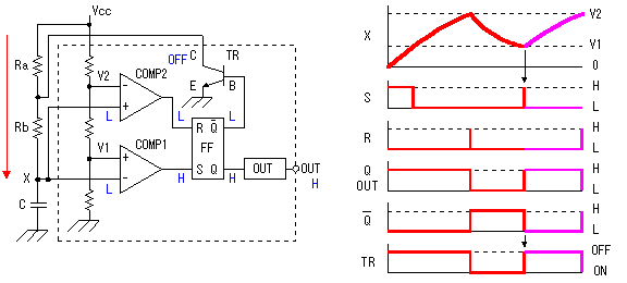
Output's reverse (2)


Because TR becomes ON, as for the electric charge of capacitor(C), it continues the discharge and the voltage of the X point falls. When the voltage of the X point becomes equal to or less than V1 of COMP1, the output of COMP1 becomes the H condition and the S terminal of the FF becomes the H condition. This changes the Q of the FF to H and changes into the L condition. Because became the L condition, TR becomes the OFF condition and the discharge from capacitor(C) stops. The electric current flows through Ra and the Rb again in capacitor(C) and the electric charge begins to store up. When the electric charge begins to store up in capacitor(C), voltage of the X point begins to go up and the output of COMP1 becomes the L condition immediately. After that, it repeats this operation and the signal of the square wave is output.

When charging (accumulating the electric charge) capacitor(C), the electric current flows through Ra and the Rb and in case of the discharge (missing the electric charge), it passes only the Rb. So, the time of the charging and the time of the discharge are different. By making the Rb compared with Ra big, the difference of both becomes small but can not make the same at all. To make the same, it is good if Ra is 0 ohm, but in the case, Vcc is directly connected with TR and TR has broken. Don't make Ra = 0 ohm absolutely. If doing the ratio of Ra and the Rb by several times, in case of the practical use, there is not a problem.

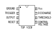
Timer IC ( 555 )

There are a lot of second sources in 555 because the circuit is simple and is with a good performance.
The second source is the IC to be selling by the similar function from the other manufacturer. The pin arrangement is the same and it is possible to replace.
There is an energy saving type of the CMOS, too


Resistor

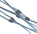
As the resistor, I am using the type that the permission electric power is 1/8 W. More than 1/8-W resistor can be used, too. In the case, the size of the resistor becomes big. This time, 1/8-W resistors are used to make a circuit compactly.  


Capacitor

A multilayer ceramic capacitor is used for the capacitor to decide an oscillation frequency. The capacitor with good temperature characteristic should be used for this capacitor. The capacitor with good temperature characteristic is the capacitor where little change of the value occurs even if the ambient temperature changes. The polypropylene capacitor is a capacitor with good temperature characteristic. However, the precision of the oscillator doesn't become good even if only the temperature characteristic of the capacitor is excellent.


IC socket

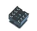
The IC can be put to direct to the printed board, too. This time, a socket is used.


Calculation of the frequency of 555 oscillator


The oscillation frequency of this oscillator is fixed by the value of capacitor (C) and resistor (Ra) and resistor (Rb).
Roughly oscillation frequency can be calculated by the following formula.
Because there is an error of the part, the oscillation frequency of the actual circuit is sometimes different from the calculated value little.


Unit f : Hz / C : Farad / Ra and Rb : ohm

It is possible to calculate by the following formula in the time that the output becomes H level and the time which is made an L level.


The time that the output becomes H level (tH)


The time that the output becomes L level (tL)


The frequency (f)


It is as follows when calculating at the value of the circuit this time.

The time that the output becomes H level (tH)
tH= 0.693 x ( Ra + Rb ) x C
= 0.693 x ( 5.6 x 10³ + 47 x 103 ) x 0.01 x 10-6
= 0.365 x 10⁻³


The time that the output becomes L level (tL)
tL= 0.693 x Rb x C
= 0.693 x 47 x 103 x 0.01 x 10-6
= 0.326 x 10⁻³


The frequency (f)
f= 1 / ( tH+tL ) = 103 / ( 0.365 + 0.326 )
= 1.45 x 103

= 1.45 (kHz)


The oscillation frequency of the made circuit was to 1,114 Hz be with the +5V power.
The difference with the calculated value seems to be the factor that the error of the part is big. I attempted to change 555 (different manufacturer) but the oscillation frequency was the same approximately.


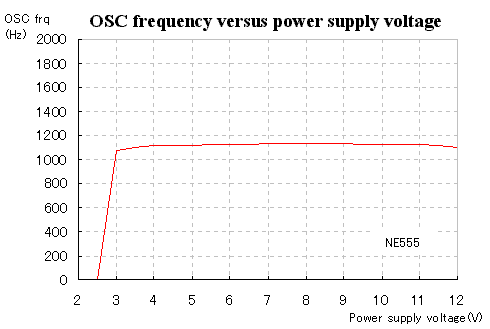
I measured the change of the oscillation frequency by the change of the line voltage.


The oscillation frequency is stable at more than +3V voltage.
It is the most stable in the voltage for 7V to 9V and it is the change of about ±1Hz(±0.1%). 

CHARGE COUPLED BI-DIRECTIONAL POWER MOSFET RELAY

The circuit uses an inexpensive C-MOS inverter package and a few small capacitors to drive two power MOS transistors from a 12v to 15v supply. Since the coupling capacitor values used to drive the FETs are small, the leakage current from the power line into the control circuit is a tiny 4uA.


Only about 1.5mA of DC is needed to turn on and off 400 watts of AC or DC power to a load.

Thursday, February 18, 2010

Move it with a VFD - Part 1

A VFD is a Variable Frequency Drive. It works with AC motors and sets
them into motion. It does so by varying the frequency of the voltage
supplied to them. There you go. That's it. Simple... but now let's see
some details.

The VFD controls two factors of the motor... speed and torque. As you
may remember from your school days, torque is a rotational force and
speed is ... well... speed. Combine the 2 and you get into horsepower
but that's a topic for another issue.

An induction motor (real commonly used by folks in the industrial
factories of the world) would rotate at a fixed speed that is
determined by the frequency of the voltage supplied to it.

Alternating current (i.e. AC)applied to the motor windings in the
'stator' produces a magnetic field that turns the motor shaft. We vary
the speed of the motor shaft by either changing:
1- The frequency of the AC applied to the windings
2- The number of magnetic poles in the windings

So, using a little math... and I mean a 'little math'... we can
calculate the speed of the motor. Just use the formula:
(120 * frequency) / number of poles = speed

If we supply a 50Hz voltage to a 4 pole motor and use the formula
above we can see that we will be turning the motor shaft:
(120 * frequency) / number of poles = speed
(120 * 50) / 4 = speed
(6000) / 4 = 1500rpm (Revolutions Per Minute)

So, if we examine the formula above a little closer, we can see
that if we want the motor to go faster we can increase the frequency
of the AC voltage applied to the windings. If, for example, we change
from 50Hz to 60Hz in the example above we get:

(120 * frequency) / number of poles = speed
(120 * 60) / 4 = speed
(7200) / 4 = 1800rpm (Revolutions Per Minute)

So, now instead of turning at 1500rpm we're flying at 1800rpm.

How else can we change the speed? Well as we read above we can also
change the number of poles our motor has. So, if for example our
motor had 8 poles in the original example we'd be moving at:
(120 * frequency) / number of poles = speed
(120 * 50) / 8 = speed
(6000) / 8 = 750rpm (Revolutions Per Minute)

So, now instead of turning at 1500rpm we're crawling at 750rpm.

Trouble is, however, that the poles are a physical 'fact' of the motor
so we can't just change them on the fly. We'd have to change the whole
motor! What good is that if we just want the speed to vary?
No good...

So, you can see that the best way for us to change the speed of the
motor is to 'vary the frequency' of the voltage being applied to it.
Can we do that? Sure we can... with a Variable Frequency Drive (VFD)!

Stay tuned as next time we'll see how the VFD actually works along
with it's relationship to our powerful friend 'torque'.

Wednesday, February 17, 2010

Creating motion with stepper motors


Last time we covered stepper motors and how they are used with a plc
to control motion. We simply send pulses out the plc and into the
stepper motor driver. The driver converts those pulses into motion
through the motor. 1 pulse = 1 degree of motion, for example.

Creating motion with stepper motors is arguably the most popular form
of creating motion in a controlled way. The trouble is that there is
no verification that the motion actually occurred. Huh? In other words,
just because we told the motor to turn 5 times doesn't necessarily
mean the motor actually did what we asked it to.

How can that be? If we send out enough pulses through the plc to have
the motor turn 5 times we should expect the motor to do so. Right?
Well, sometimes our expectations aren't always met...

What would happen if there was a jam in the motion system? The motor
tries to move but can't. Not good. That can (probably will...) cause a
problem for our machine.

Let's say we're applying labels to various sized boxes. This morning
we're making product A which has a large box. Our plc program has the
stepper rotate 10 times so we know the box is in the proper position
and the label can be applied.

Things are going great. The boxes are moving down the conveyor and the
labels are being applied as expected. Time for lunch and we change our
products. We now use a product that weighs twice as much as the previous
one but the box size is the same. So we use the same plc program and
we expect things to work out great. Correct?

Not so much... the extra weight of the product is causing stalling of
the stepper motor and eventually labels are being misapplied and
general chaos sets in. A bad day at the office... for sure.

The problem here is that the system is an 'open loop' system. There
are no checks performed to verify that what we wanted done actually
got done. We told the stepper motor to move but we didn't verify that
it had actually done so. We have performed a 'one way' type of
communication.

In many simple applications or those where there are checks via
sensors, for example, a one way type of communication would be fine.
However, in the example above without any checks it's obviously not a
good situation.

In that case we need a 'two way' type of communication system. Instead
of being an 'open loop' system we need to close the loop by generating
some feedback about what events have occurred. But how?

The answer is quite simple. We need to do an action and verify the
action resulted in whatever it was we wanted. If we tell the stepper
motor to turn 5 times we need to verify it did. An easy way to do this
is with our old friend... the encoder. (Remember how they worked from
a few issues back?)

So, let's return to our great 'moving the box' application. We move
light weight boxes down the conveyor by sending out 5 pulses to the
stepper motor. We previously had no idea if the motor actually moved
but we knew we asked it to move.

If we now add an encoder to the system we can easily verify if the
movement of the motor actually happened. The encoder will give back a
pulse to the plc for every x-degrees the motor shaft rotates. So, if
we tell the motor shaft to rotate 5 times, and each revolution is
10 pulses from the encoder, the plc can look for 50 pulses. (i.e.
10pulses x 5rotations = 50)

If the plc 'sees' 50 pulses come from the encoder it knows the shaft
has rotated the proper number of rotations. If it doesn't see that the
rotation has actually happened as expected (i.e. less than 50 pulses
have come back) it can react accordingly. Of course, that reaction will
have to be programmed into the plc program.

Now, we have added feedback to the system and closed the control loop.
We therefore refer to this type of system as a 'closed loop' system.
The control loop is closed because we can do something and then verify
that it was actually done.

A closed loop system can be created in many ways. The key point is that
we need feedback on the action. How we react to the feedback is going
to be dependant upon the system.

Next time we'll see a motor with 'built-in' feedback to make our
closed loop system of motion control 'a pleasure' to use.

Tuesday, February 16, 2010

AS-Interface... Let the Sensors Do the Talking


AS-Interface is a convenient bus for us... when we don't need to pass a lot of data back and forth. It's primary intention is for your plc to be used to with simple sensors and actuators... Hence the
meaning of AS-Interface is actually 'Actuator Sensor-Interface'.


ASI came into the world back in 1994... the good old days where many (most?) plc vendors were pushing out their buses. All felt they should be world standards and (to make a long story short) to this day
we have no 'world standard'. But ASI is in the mix.

ASI was introduced by Siemens and based around ProfiSafe (which was in  itself from Profibus DP). It is an 'open standard' which means there's an -unbiased- trade group that maintains the standard. Anyone can
get (buy) a copy of the standard and develop a product based on it. IEC 62026-2 and EN 50295 are the standards numbers.

It is a Main/Sub type of network meaning we can have one main unit (usually our plc) connect to many sub units. Actually, depending upon the version of ASI we're using, we can have up to 31 or 62 sub units.

Generally that is large enough for all but the biggest networks. Remember, we're just connecting our plc to sensors or actuators so 62 sensors/actuators is quite large. But again, large to some is small to others...

ASI is a two wire network and very simple to use. Power and data both flow over the cables. The cables are Ungrounded, Unterminated and Unshielded (That's a lot of Un's...). We can connect our network in
either ring, bus, star or tree fashion.

Distance is also quite good. We can go all the way out to 100 meters  (over 300 ft). And if we use a repeater we can go out to about 600 meters... hopefully that's far enough for us to go. We can also  connect a maximum of 124 inputs(31 subs x 4 inputs each = 124) and 124 outputs (31 subs x 4 outputs each = 124) according to the original spec (2.0) or 248 inputs (62 subs x 4 inputs each = 248) and 186
outputs (62 subs x 3 outputs each = 186) according to the 2.1 spec.

The cables can be connected to a power supply to transmit power to the devices on the network. Maximum power can be 8 amps at 24 VDC. Devices are simply 'tapped' into the cables at any point making installation a very simple process. The cables are typically called 'yellow cables'
because they are typically... 'yellow'.

We use 3 operating modes to communicate in. they are:
I/O data transfer mode- The inputs and outputs of connected sub units are read from and written to in this mode. So, we transfer the status of the input/output devices to/from the plc.

Analog Value transfer mode- version 2.1 allows us to work with analog  data. Here, that data is transferred and processed.

Command mode- Here we can send/receive various commands. Some examples are address setting of the sub units, diagnostic information reading from the subs and transferring various parameters and setting
data.

How do we get/send the actual data from the sub units to the main unit?
Well that can be accomplished in one of two ways. The first way is arguably more popular. It is cyclic polling. This simply means that at a given point in time we have the main unit ask the subs for some  specific data. In other words, the main unit polls the subs for their data. The subs get the request and send back their data.

The second way is by having the sub units send their data at specific  time cycles. This is simply called cyclic data reception because we receive the data during specific cycles.

Maximum cycle time is ~5 ms when 31 subs are connected or 10 ms when  62 subs are connected. It's based on the fact that each cycle is 150 us and there are 2 cycle required for administration... so we get:
(2x150) + (31x150) = 300 + 4650 = 4950 us or 4.95 ms.

Well, hopefully that's enough of the basics to get you thinking as to  whether or not this bus is right for your needs. Next time we'll see how it actually works...

Omron host link

This time we'll discuss one of the oldest communications protocols defined by Omron... Host Link. Host Link allows a single computer to talk with one or more PLCs. It can also allow more than one computer to talk with several PLCs, depending on the mode it is in.


One point that should be mentioned is that just because you are using the Omron protocol doesn't mean you have to be using an Omron PLC.On the contrary... it is an open protocol so many vendors actually support it. This means, even more, that so we should know about it!

So, how do we use it? Let's see. First we need to figure out our setup. If we are using a single PLC connected to a single computer we will use what's called a 'single-link' system. This is the most common setup. We are using the computer to log data or just make simple changes to the PLC.

If we are using a single computer but are connected to multiple PLCs we will use what's called a 'multiple-link' system. Gee... the naming makes sense, doesn't it?? And by the way, as we noted, we can also  connect multiple computers and multiple PLCs together to really have some good communications going on... but this is far less common.

So, how do we connect everything together so they can freely talk with each other? Well, we use the same 'stuff' as we would when using RS-232 or RS-422. Actually, we commonly talk over those communications
lines.

If we are using RS-232 then we are going to be limited to a maximum distance of ~45ft (15m) between the computer and the PLC... plenty of distance for most applications.

If we are using RS-422 then we have a much longer cable allowance...
we can use up to ~1500ft (500m). If you need to be farther than that distance from the PLC then a different technology is probably better for your application.

Why use RS-232 or RS-422? Simple, if talking with more than one PLC at the same time then use RS-422. If you're only talking with one PLC then use RS-232. The only exception is when you need to talk with one PLC but must be more than ~45ft (15m) away from the PLC.In that case RS-422 is also the best choice for your application.

So, what can we do with Host Link? Answer, what do you want to do? We can read memory out of the 

PLC. We can write data to the memory of the PLC. We can force some inputs/outputs to be on/off.

Probably the most common use of Host Link protocol though is in using an HMI (Human Machine Interface). In case you don't know, an HMI is basically the operator interface panel on a machine that gives/takes
instructions form the operator and translates those human understandable instructions into something the PLC can interpret. It is sometimes also called an MMI... as in Man Machine Interface.

When using an HMI, we need to often get data from the PLC and display it. Perhaps we want to see a product count or a temperature/pressure or maybe we just want to see an alarm condition. Instead of just seeing 'error 64' or whatever, we can program the HMI to display 'over temperature alarm on cookie oven', for example.

The HMI would communicate with the PLC to get this type of data. The  language that it will talk (in this example) will be Host Link.remember, however, that the PLC and the HMI must both have built-in
Host Link capability... otherwise they won't be able to understand  each other.

Well, that's a really brief overview of what Host Link is and what it can do. Next time we'll see the actual language itself and follow a conversation between a PLC and a computer to really get an  understanding of the process. You'll see things on a byte level and realize that it isn't all 'black magic'... we can understand it

stepper motor

A stepper motor is a motor that does just what its name implies...
it moves by 'stepping', just like we do... well kinda like we do anyway. We don't walk (i.e. step) in a single fluid motion. Rather we move in a start/stop type of motion whereby we move a leg and then stop
it and then move another leg and stop it. By repeating that process we move a certain distance.

A stepper motor does something similar to our walking. It moves a few degrees and stops. Moves a few degrees again and stops. As you cannow understand, it is not continuous movement. Instead, it is start/stop
movement. Move, stop, move, stop, move, stop, etc.

On the other hand, a 'typical' motor does not work that way. A typical motor (is there really such a thing as a 'typical' anything??) does not work that way. Nope, we just give it a voltage and it spins away as long as the voltage is there. Nice and fluid motion as opposed to our start/stop motion in the stepper motor.

So, we can think of a 'typical' motor as an analog motor and a stepper  motor as a digital motor. The analog motor can vary position at any point in its movement. The digital motor can't vary its motion to any point but rather can vary within predetermined distances.

How does it know where to move to? That's a good question. It needs to have a driver. The driver controls its movement. It gets movement data (i.e. pulses)from a device capable of generating pulses. More often than not the pulses come from a plc, of course. The plc often has single axis capability built into it but in recent times there are also extension modules that plug in to the plc base unit and give it the capability to control more than one axis.

The pulses coming out of the plc are received by the stepper motor driver. The driver converts each pulse it receives from the plc into'motor motion'. If the motor moves 1 degree for every step and the plc sends 5 pulses the motor will of course move 5 degrees.

How about speed? Well that will depend upon how fast we can generate the pulses out of the plc. Trouble is, we can generate the pulses real quick out the plc... many times too quickly. Too quickly because we need to remember that the stepper motor moves like we do. Why does that matter? Let's see...

We can't just go from standing still to an all out sprint speed. Even the fastest runners in the world can't start from a standing still position and be instantly at sprinting speed. The reality is that they  need to gradually move faster and faster until they get to their all out sprinting speed. Once the runner is at full speed they will continue at that speed before stopping.

The same thing will apply to stopping. The runner can't just go from a full all out sprinting speed to a full stop. (unless he runs into a brick wall... ) The stepper motor has the same issue. It can't just go from a 'cruising speed' to a dead stop. It needs to slow down gradually.

So, to get around this 'fact of life' we start running slowly while gradually building up our speed until we get to our maximum cruising speed. Before coming to a complete stop we also slow down gradually.


Same thing for the stepper motor. We send out pulses at a slow speed and then gradually increase the speed of the pulses until we get to the maximum speed we need to cruise at. Then we send out slower  pulses until we safely bring the stepper motor to a complete stop.

This starting slow and finishing slow type of motion is called ramping the motor. We slowly ramp up to speed and then we slowly ramp down to speed. This is a 'must' when using stepper motors. If you don't do this your motor may stall instead of move. That would be bad...

How do we create this ramping functionality? No worries, the plc will take care of creating 'the ramp' for you. Generally you just need to give the system some basic parameters such as the number of pulses to generate and the maximum speed.

So, if the system needs to be complex enough to have a special plc module or programming functionality why do we need it? Why not just use a 'typical motor'?

The answer is simple. Precision. When you need to move a semi-precise  distance you need something like a stepper motor. A 'typical' motor will not give you the same or even close to the same precision as a stepper motor will give you. On the other hand, if you need speed or ultra-high precision movement a stepper motor might not be the best choice for you.

So, what qualifies as semi-precision? Generally, a stepper motor with  high precision would be capable of moving about 500 steps per revolution. That equates to about 0.72 degrees for every step. (i.e. 360degrees / 500steps = 0.72 degrees per step) We can also do what's called micro-stepping whereby we can get approximately double that precision. To do that we move in half-steps with a more capable motor driver. But if you need high-precision movement there are some better motor options. More on that next time...

Servo motor


Servo motors are generally DC motors. They are simple devices but can
do incredibly precise movement when used properly. DC motors are used
in servo control because they can have their speed varied in a very
simple way. Simple is good...

How simple is simple, you ask? Well, all we really do is vary the
voltage going to the motor and the speed will change. More voltage
means faster speed. Less voltage means less speed. See, DC motors are
really simple. Controlling them precisely... well that's another story.

Remember our story from last time where we talked about open loop vs
closed loop control. Closed loop control provides feedback to close
the control 'loop'. We tell the motor to move and we use an encoder or
another method to actually verify that we have moved to where we said
we wanted to go.

We 'closed the control loop' by feeding back our actual position to
verify we moved. If we didn't move to where we needed to be because
maybe there was a heavy weight on the conveyor we're turning, for
example, the encoder would let us know. Then we could adjust our
position by sending more pulses to the motor.

A servo motor is an example of closed loop control. The servo motor
typically has an incremental encoder on it's back monitoring the shaft
positions. If the shaft turns then the encoder tells us so. If it
doesn't turn, even though we told it to, we won't get any pulses out of
the encoder. Again, it's a closed loop system.

So, the plc tells the servo controller where to move the motor. The
controller sends the appropriate voltage pulses to the motor and the
motor moves. The encoder on the motor shaft verifies the movement
happened. If we tell it to move at 700rpm (revolutions per minute) and
the encoder only gives us pulses at 650rpm then we send the motor more
voltage to increase the speed to 700rpm.

To get some accurate control of the position and speed of the motor is
where the fun starts. We can't just send it a voltage and expect high
precision in the end. We must constantly monitor and adjust what's
going on in the 'system'.

Generally we are concerned with two situations... starting/stopping
and continuing movement. We refer to the starting/stopping part of the
cycle as the transient state because it's in a... transient state. In
other words the speed of the motor is transitioning (changing) from
stop to movement or movement to stop.

Once the motor is moving along we enter the steady state because we are
no longer transitioning from stop to movement. Rather, we are moving
along at a semi-steady speed.

To work in both 'states' we need to 'compensate' the motor.
Compensating the motor simply means we need to constantly adjust the
motor so it does what we want it to... move correctly.

We compensate the gain and bandwidth of the servo system. The gain is
the ratio of the output signal to the input signal. It's basically
how much the input signal is amplified or increased and effects the
accuracy of our movements.

A large gain allows the servo system to make small movements in a very
accurate way. This is a large feature of servos. The gain let's us get
close to the speed we desire by adjusting the actual speed that we are
moving.

The bandwidth is a measure of it's frequency. By frequency we mean that
it's a measure of how often or fast our system can respond to a change.
The wider or larger the bandwidth of our system is the faster we can
respond to changes.

So, a faster response is a quicker response which, of course will
result in more accurate movement in the end. The more accurate
movement happens because we are able to react to changes quicker. In
this case quicker is better...

In general, more gain and bandwidth are good things for our application
to use. Of course, different servo systems will allow different gains
and bandwidths. They are generally a limitation to the hardware that
we are using and each application will have it's own requirement. But
we only need to note that the system is tuned by the compensation we
provide it.

So, when you're looking for high speed and accuracy in your motion
control consider a servo motor over a stepper motor. You will be
pleased...

Saturday, February 13, 2010

Factory Intelligent Network Services

FINS(Factory Intelligent Network Services) is a protocol used by Omron plcs. This protocol allows the plc to communicate with other plcs, external devices, and PCs.

Most commonly, this protocol is used to communicate over Ethernet. In that case, we can use FINS/UDP or FINS/TCP. Basically, if we're using Ethernet to talk directly to other plcs on the same segment we'd want to use FINS/UDP. Otherwise, FINS/TCP offers better communications quality and should be used. (That's a generalized view...) The protocol can also be used over their HostLink protocol. When used
in this way, however, we are usually directly connected via our pc.

When FINS is used over Ethernet we can have up to 254 devices and our  message length is limited to 2012 bytes... although that can be a large message.

When using FINS via HostLink we can have up to 1 device connected via  rs-232 or up to 32 devices via rs-422. In this case our maximum message size is held back to 542 bytes.

FINS works by using a command/response type system. In other words, we  send a command and wait for a response. Simple theory... right? Well we can also send commands such that a reply is not needed. Or we can send a broadcast message to all devices connected. So, it's flexible.

How do we know which device should get the message when a bunch are  connected? Simple, we give each one an address. Then we send the command to that address and the other devices will ignore it. (If  we send to the address FF we are broadcasting a message to all connected devices)

So, how do we talk to the plcs then? Well if we're using Ethernet we simply bury the message into the TCP or UDP message. And if we're using HostLink we bury the message in there. Confusing? Then look a this:

For FINS/TCP the packet of data flowing would look like-
IP-TCP-FINS/TCP Header-FINS message-FCS
We took a standard TCP packet(ie message) and put the FINS data into the section that requires data. Simple.

The same would be true for UDP or HostLink. We replace the data
section with the FINS data.

What do the actual messages look like? Let's see the Ethernet commands first...

For the commands we use the format: header-command code-message The header contains:
ICF-RSV-GCT-DNA-DA1-DA2-SNA-SA1-SA2-SID
ICF - Information Control Field - This field describes if we are expecting a response, what type of data, and if we're using a 'gateway'.

RSV - Reserved - This is always 00
GCT - Gateway count - This is the maximum number of gateways allowed.
DNA - Destination Network Address
DA1 - Destination device Address
DA2 - Destination unit Address
SNA - Source Network Address
SA1 - Source device Address
SA2 - Source unit Address
SID - Service ID - This is the identity of the process it came from in
a large configuration. Make it any hex number from 00-FF.

When using HostLink the commands look slightly different. Not really different but we need to use certain specific values in certain places. The format is the same but...

We start the header with FA.
ICF - Always 80
RSV - Always 00
GCT - Always 02
DNA - 00-7F hexadecimal number which corresponds to address from 0-127
DA1 - 01-3E hexadecimal node number
DA2 - 00 would indicate it's the CPU
SNA - Always 00
SA1 - Always 00
SA2 - Always set to FC
SID - Used as a counter when data is resent. Usually should be set to
00 initially.

Well that's a very rough (and I do mean rough) overview of what happens with FINS. It is most commonly used over Ethernet to help the plcs communicate across the network. If you're using Ethernet and Omron devices you should really know the basics of the above to further understand what's going on 'under the surface'.


Tuesday, February 9, 2010

LS PLC

this is my experience using ls plc for four colour intaglio machine

Monday, February 8, 2010

How to connect LS PLC with LS touch screen

to make user friendly machine some designer using HMI touch screen

xp builder

a touch screen HMI from LS Industries

cable for CPM 2A

for you omron programer